-
How to operate MAC IV?
Analysis process of MAC IV:
1. Click “Analysis” ,and then choose the crucible (Figure 1)
 Figure 1
2. Click ”Weigh empty crucible with lid for M&V&A”(Figure 2),and then there is prompt box(Figure 3),click “Yes” .
NOTE: Please cover the crucible with lid including crucible 0
 Figure 2
 Figure 3
3. After weighing empty crucible with lid (prompt box as Figure 4),Please remove the lid of crucible including crucible 0 , click “ok”(prompt box as Figure 5 ,if you are sure that all lids of crucible have been removed including crucible 0) click “Yes”, it will weigh empty crucible without lid
 Figure 4
 Figure 5
4. After weighing empty crucible without lid , there is a prompt box as Figure 6 . Then put sample into crucible (1.0±0.01g),click “Yes” ,Prompt box as Figure 7 . click “Weigh sample for M&V&A”(Figure 8)and “Yes ”in Figure 9
Note : First put sample into crucible , second click ”Yes” in Figure 6
 Figure 6
 Figure 7
 Figure 8
 Figure 9
5. After weighing sample ,click “Yes” in Figure 10 , close the stove cover, click ”start M&V&A analysis” in Figure 11 and then click “Yes” in Figure 12
Note: do not forget to close the stove cover
 Figure 10
 Figure 11
 Figure 12
6. First we will finish moisture analysis , after finished moisture , there is a prompt as Figure 13 .open the stove and cover all crucible with lid by crucible tong ,then close the stove cover .click “ok” and “Yes ”(in Figure 13 and Figure 14). We are now starting volatile analysis.
 Figure 13
 Figure 14
7. After keeping constant temperature at 950 for 7min , there is a prompt box as Figure 15.Please open the stove cover(click ”OK” in Figure 15) and wait for temperature downing to 350℃ . When temperature down to 350℃, it will keep constant temperature for 15 min .then weighing for Volatile .
Note : DO NOT remove the lid during the volatile analysis .
 Figure 15
8. After finishing weighing for volatile , there is a prompt box as Figure 16. Please remove all lids include crucible 0 .Then close the stove cover and click “ok” in Figure 16
Note : do not forget to close the stove cover
 Figure 16
9. At last, after finish weighing for Ash , we finish this test.
 Figure 17
-
How to calibrate calorimeter of C5500?
Before you start calibrating the instrument , something must be noted :
1.Please start calibrate after 24h when you changed the water .
2.Keep the room temperature stable .
Calibrating
Calibration process:
1. Open the software , click “system setting” . Input the calorific value of benzoic acid ,change the analysis content into “Calibrating Heat Capacity By Benzoic Acid”(Figure 1 and Figure 2)
 Figure 1
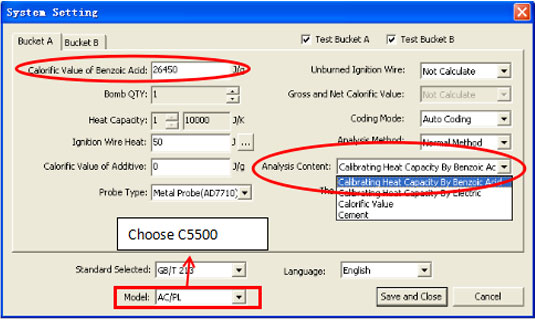 Figure 2
2. After finished setting , click “Start Analysis” and input the weight of benzoic acid (1g±0.1g) (Figure 3 and Figure 4)
 Figure 3
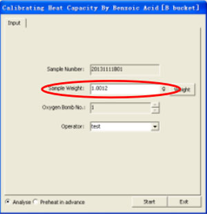 Figure 4
3. After finished analyzing 5 samples , click “Function- Calculate Average Heat Capacity” and choose those five results , click “Calculate The Average Value” , then you will get the average value and RSD , at last , click “Save” to save the value .(Figure 5 and Figure 6)
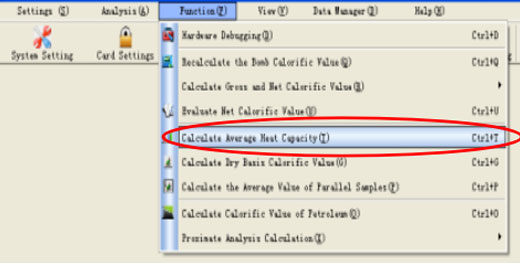 Figure 5
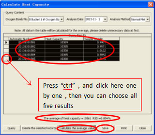 Figure 6
4. Now calibration has been finished .
Verification
After calibrating , we need to do verification to check the calibration .
Verification process :
(1) Click “system setting ” again , and change analysis content into “Calorific Value”(Figure 7)
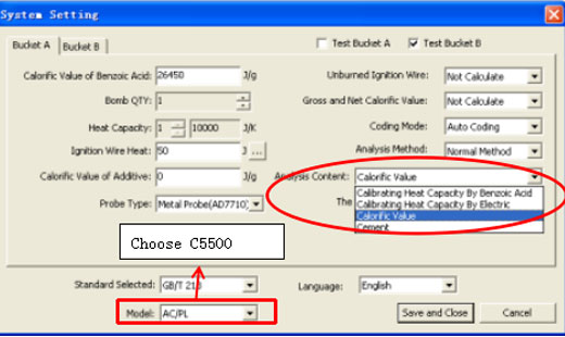 Figure 7
(2) Click “Start Analysis” (two samples or more), input the sample weight (1g±0.1g). And record the results .(Figure 8)
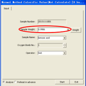 Figure 8
(3) Calculate the average value of these results . If the difference between the average value after minus 40J/g and the calorific value of benzoic acid is 60 J/g , the calibration is good .
-
How to check leakage for CHN?
1. please check the gas leakage of furnace and tank , after then check the leakage of whole gas circuit:
In software click “function-diagnosis” and then click “tank “to check tank gas leakage. Next click “furnace” to check furnace leakage . At last click “whole” to check whole gas circuit
2.Observe the flow of oxygen with the flowmeter
Click” function-system debugging-SV6-go” here the oxygen flow is 4.0L/min .If not , please find AS8 to adjust it to 4.0L/min
Click” function-system debugging-SV5-go” here the oxygen flow is 1.5L/min .If not , please find AS7 to adjust it to1.5L/min
Click” function-system debugging-SV4-go” here the oxygen flow is 0.5L/min .If not , please find AS6 to adjust it to 0.5L/min
3.When you start analysis , please observe the value of pressure 1 , during burning 3 , it must to reach 155000Pa ,
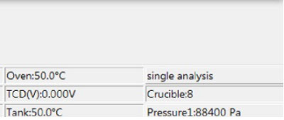
4.Please observe the piston’s position , open the left board with a 2 cm gap , then observe whether the piston can reach the top of the tank or not.
-
How to recalibrate the heat capacity of calorimeter?
Please re-calibrate the Heat Capacity as follows:
1. Select the mode to Heat Capacity determination
Select “Heat Capacity” in [setting] - [system setting] - [analysis content], input “Bomb No.” and Calorific Value of “Benzoic Acid”, then click “OK” to save it.
2. Do 3 trail tests of Benzoic acid
(1) Do 5 tests of Benzoic acid to get calorific value
If the value (the maximum value subtracts the minimum value) ≤40J, you can calculate the Heat Capacity: Enter [functions] - [Calculate Average Heat Capacity], select the 5 tests’ results, select “recalculate” and “save heat capacity”.
(2) If the value (the maximum value subtracts the minimum value)>40J, please do one more test.
a. In the 6 tests’ results, select 5 tests’ results which can reach requirement of value (the maximum value subtracts the minimum value≤40J). Then use the 5 results to calculate Heat Capacity: Enter [functions] - [Calculate Average Heat Capacity], select the 5 tests’ results, select “recalculate” and “save heat capacity”.
b. In the 6 tests’ results, if any 5 results cannot reach requirement of value (the maximum value subtracts the minimum value) ≤40J, please redo 5 tests again.
(3) Enter [system setting] - [setting] first and select the mode to calorific value determination. Then you can test the standard sample and compare the result with standard value.
-
How to set the program of MF6000?
For the common program, you need to set up the temperature what you want first, the default temperature is 920℃. You can set as the following steps:
1. Press "Reset" two times, then press "setup”, after input 622, press “Start”, the "Temperature Screen" will show the first temperature. After Input the first aim temperature, press "Setup", then the "Time Screen" will be modified, input the time for the first aim temperature, then press "Setup". The first temperature and time is finished.
2. Setting the second temperature and time according the same step, After Input the aim temperature, press "Setup", then input the time for the second aim temperature/"Setup" /input the third aim temperature /"Setup" /input the time for the third aim temperature/"Setup"/then save automatic. It's the end for setting
3. If you want run this program, press the common program key and start into key, it will be ok, it is easy to change this program as the above, and there is no relationship with the calibration temperature.
-
Whether C5500 Automatic Calorimeter can update from bench-top into vertical type
In order to save the space, a Vertical type calorimeter from CKIC is available. CKIC give the solution to change from Bench-top type to Vertical type
Step 1: Prepare the spare parts required
Name ERP No. Specification Quantity Unit Picture
Bracket 212009048 C5500B-00F 1 Pcs
Clamp 3111300038 φ60 2 Pcs
Bellows 50431383 φ54.5*48 1.5 m
Pipe 3090201003 φ15/φ11 6 m
Step 2: Adjust the horizontal of the bracket
The horizontal of the bracket is very important to keep the stable performance of the calorimeter. Put the spirit level on the bracket, adjust the
four feet on the floor to reach the horizontal.
Step 3: Load the chiller and controller
The chiller load on the bottom while the controller on the top Controller Chiller.
Step 4: Follow the number to change the pipe from the side to the top
Each hole from Side(B) to Top(A) has already been marked with numbers 1/2/3/4. Take out the pipe from Side(B) and follow the numbers to connect to inside of Top(A).
Step 5: Cut the pipe and hidden into the bellows
Step 6: Connect the pipe from the chiller to the controller
Follow the number again to connect the pipe from Top(A) from the chiller to Side(C) from the controller.


 Figure 1
 Figure 2
 Figure 3
 Figure 4
 Figure 5
 Figure 6
 Figure 7
 Figure 8
 Figure 9
 Figure 10
 Figure 11
 Figure 12
 Figure 13
 Figure 14
 Figure 15
 Figure 16
 Figure 17
 Figure 1
 Figure 2
 Figure 3
 Figure 4
 Figure 5
 Figure 6
 Figure 7
 Figure 8


